The SP53 committee in developing ISA-53 Graphic Symbols for Distributed ControlShared Display Instrumentation Logic and Computer S ystems The key elements of ISA-53 have been incorporated into ISA-51 and it is the Societys in tent to withdraw ISA-53 after publication of this revision of ISA-51. ISA 51-1984 R1992 Instrumentation Symbols and Identification.
Software Plantengineer X Visual
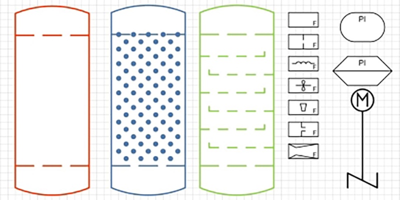
We recommend using the table of contents to navigate this comprehensive directory of common Piping and Instrumentation Diagram symbols.
Isa p&id symbols for visio. Choose whether to create a new shape data set a set based on the currently selected shape or a set based on an existing shape data set and then click OK. - 3 - ANSIISA-51-2009 Preface informative This preface is included for information purposes and is not part of ANSIISA-51-2009. Here is a list of symbols for various types of valves used in process industry.
Instrumentation Symbols PRO is a graphic instrumentation symbols software developed for Autodesks AutoCAD Microsofts Visio for Windows 7 and 8 ZWsofts ZWCAD for Windows 7 and Windows 10 and Dassault Systemes DraftSight Pro. These ISA instrumentation symbols provide the user with graphic symbols to be used during the engineering design and layout for various. The symbols are furnished in DWG WMP and DXF file formats allowing them to be employed with Visio AutoCAD and most other CAD software platforms plus many other.
PIDs Piping Instrumentation Diagrams and PID Valve Symbol Library. PID symbols exist for all major components and lines such as valves vessels instruments pumps compressors and towers. This product is graphic symbols software developed for the Microsoft Visio software platform.
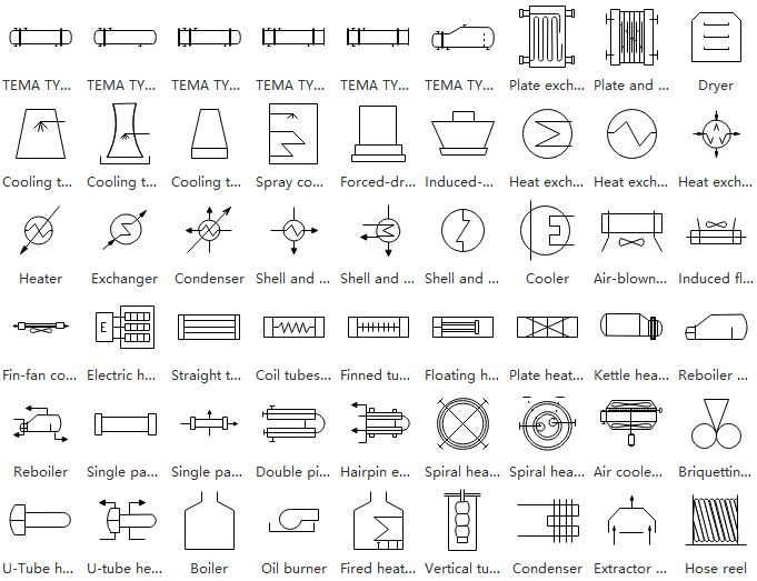
Pumps and Turbine PID Symbols. Standard PID Symbols Legend Industry Standardized PID Symbols Piping and Instrument Diagram Standard Symbols Detailed Documentation provides a standard set of shapes symbols for documenting PID and PFD including standard shapes of instrument valves pump heating exchanges mixers crushers vessels compressors filters motors and. ISA Instrumentation Codes used in Process Control Systems - The ISA standards and symbols are important for the PIDs and documents describing the process control system.
The PID is the primary schematic drawing used for. PID - Piping and Instrumentation Diagram - Schematic illustration of a functional relationship between piping instrumentation and system components. This CD-ROM provides symbols from the ISA standards S51 S52 S53 and S54 converting the graphic symbols for instruments into clip-art files that can inserted into PIDs loop diagrams and other documents.
Type of valve employed depends on nature of fluid flow control required operating pressure and temperatures as well as surround atmosphere. It provides users with graphic symbols to be used during the engineering design and drawing layout for a variety of. The ISA S51 ISO 10628 and BS 5070 cover the standardization of PID symbols and guide process engineers in their plant design activities.
Click Add and then type a name for the shape data set. Intelligent PID Symbols Industry Standard PID Symbols Libraries with attribute data for a Spec-Driven pipelines Powerful Drafting Features Intuitive PID creation with simple Drag Drop with add-on automatic features Quality Checking Tool. This lets them be easily used in MS-Visio AutoCAD and other computer aided design CAD platforms and spreadsheet programs.
PID symbols and notations One area of PIDs that is standardized are the instrumentation symbols the key to being able to understand PIDs. 102 Durham NC 27703 Email. There are few ISO and British standards available that provide symbols and best practices to draw PFD and PID such as ISA S51 BS 5070 and ISO 10628.
It also adds AutoSnap AutoLegend and AutoTagging capabilities to the Visio platform. ISA 51 Instrumentation Symbols and Identification ISA 52 Binary Logic Diagrams for Process Operations ISA 53 Graphic Symbols for Distributed Control Shared Display Instrumentation Logic and Computer Systems ISA 8401 Application of Safety Instrumented Systems for the Process Industries. This graphic symbols software developed for the Autodesk AutoCAD platform and the Microsoft Visio software platform sold separately provides users with graphic symbols shapes to be used during the engineering design and drawing layout for a variety.
Based on the widely used ISA standard ISA-51 Instrumentation Symbols and Identification. Visimation Inc 4580 Klahanie Drive SE 225 Sammamish WA 98029 ShapeSource by Visimation is your one-stop source for Visio stencils Visio shapes and Visio templatesBrowse our eCommerce website for both free and paid stencils for Microsoft Visio 2013 2010 and older versions of Visio for creating professional quality technical drawings. Visimation Inc 4580 Klahanie Drive SE 225 Sammamish WA 98029 ShapeSource by Visimation is your one-stop source for Visio stencils Visio shapes and Visio templatesBrowse our eCommerce website for both free and paid stencils for Microsoft Visio 2013 2010 and older versions of Visio for creating professional quality technical drawings maps diagrams.
To be of continuing value this standard. PID symbols are a graphical representation of physical equipment that installed on the field. This software is based on the widely used ISA Standard ANSIISA-51-2009 Instrumentation Symbols and Identification Copyright 2009 ISA.
A piping and instrumentation diagram PID is a graphic representation of a process system that includes the piping vessels control valves instrumentation and other process components and equipment in the system. Instrumentation symbols appearing on diagrams adhere to ANSIISAs S51-1984 R 1992 standards. Media piping class material pressure temperature.
Visio PID features Industry Standard PID Symbols Libraries Intelligent standard libraries ANSI ISO 10628 IEC 62424 ISA-51 and dynamic symbols with associated attributes and relationships All symbols and drawing elements have associated data properties eg. For engineers and designers knowing the symbology legend can also improve PID collaboration. The most common PID symbols are listed below.
Knowing what the various symbols represent is vital to a user understanding a PID. PID Symbols for Pumps. PID Symbols for Valves.
International Society of Automation 3252 S. PID and PFD Symbols. To add or modify shape data in the Shape Data Sets dialog box select the shape data set and click Define.
The CD will help engineers design standards-conforming PID with greater accuracy consistency and speed. This standard has been prepared as part of the service of ISA The International Society of Automation toward the goal of uniformity in the field of industrial automation. Symbols are provided for the following standards.
Piping components pipes flanges and. Many types of valves are required in a process plant for flow regulation or onoff purpose. The PID standard issued by PIP is enclosed in PIP PIC001 Piping and Instrumentation Diagram Documentation Criteria which defines the PID format drawing size item layout tag format text arrangement etc symbols drafting rules and tagging and numbering scheme for the equipment tanks exchangers pumps reactors etc piping piping lines valves and fittings and.


No comments