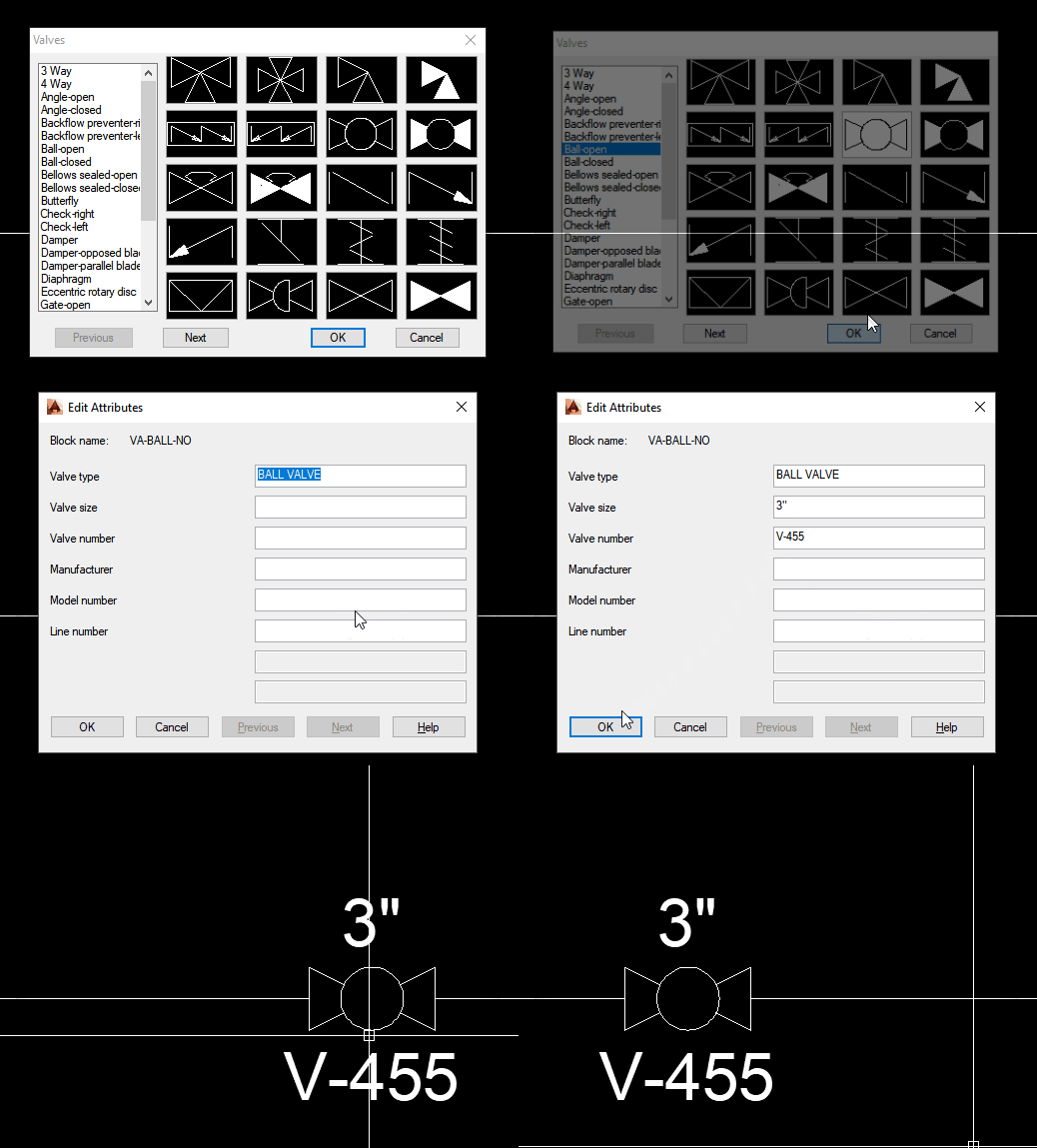
Ball Valve Normally Closed. Pressure Relief Valve Symbol Vacuum Relief Valve Breathing Valve or PressureVacuum Relief Valve Pressure Rupture Disc Vacuum Rupture Disc You may also like Crude Oil Refining Process Design.

P Id Symbols Library V3 0 For Draftsight
ISA PID symbols will inform the Process Operator and Control Room Operator where the control components are located.
Isa p&id valve symbols. A piping and instrumentation dia-gram is similar to a process flow diagra m in that it includes an illustration of the major equipment. I like the fact that the PID indicates the fail position FC as well as the valve type it. Symbols conform to ISA Standard 51-2009.
The ANSIISAs S51 standards are what this guide will be using to communicate consistently. Control Valve with. The pipe lines are represented by lines connecting to each side of the valve symbol.
Suddenly you cant even see the reactor for all the ISA symbols littering the page. B - Users choice. To be of continuing value this standard.
You may know exactly what P means or what D means or what a PID contains but the person in the facility down the road probably doesnt agree. The primary purpose of using codes and symbols is to enable the various instrument functions required in a process to be clearly and concisely represented on Process Flow Diagrams PFD and on Pipeline and Instrumentation Drawings PID. Legend Symbol Valves.
- 3 - ANSIISA-51-2009 Preface informative This preface is included for information purposes and is not part of ANSIISA-51-2009. Y - Relay compute convert. However the PID includes much more detail about the piping associated with the process to include manually oper-ated blocking valves.
VALVE_COMPLICATED shows how one client shows an onoff valve. Consider the examples below. Angle Valve Hand Operated.
Position Switch - High Level. M - Middle intermediate. A PID piping and instrumentation diagram is a graphic representation of the piping and system components in your process that uses standard symbols and annotations.
Interlock number and proper symbol dcs or plc will be shown on process pid. Balanced Diaphragm Gate Valve. Symbol legend sheets are included.
Commonly used PID symbols Piping and Instrumentation Diagram symbols for safety valves. The SP53 committee in developing ISA-53 Graphic Symbols for Distributed ControlShared Display Instrumentation Logic and Computer S ystems The key elements of ISA-53 have been incorporated into ISA-51 and it is the Societys in tent to withdraw ISA-53 after publication of this revision of ISA-51. Piping and Instrument Diagram Standard Symbols Detailed Documentation provides a standard set of shapes symbols for documenting PID and PFD including standard shapes of instrument valves pump heating exchanges mixers crushers vessels compressors filters motors and connecting shapes.
For instance the P in PID may stand for Piping or Process. Z - Driver actuator. Not all PID elements are standardized but the instrumentation symbols follow a standard set by the International Society of Automation ISA.
Exchangers like the one featured on the PID and in the picture are temperature-changing. Standard that specifies what information should be included on a PID or even for that matter the meaning of the letters PID. For valves located in pits with extended valve stems actuators limit switch and positioner will be located outside the pits.
Valve Symbols for PIDs The generic symbol for a 2-way valve is two triangles pointing to each other with the tips of the inner points touching. It plays a big role in the management of a physical process. Contains 335 PID symbols in dwg format and 78 custom line types.
DCS control components that are viewable andor accessible on DCS screens will have ISA symbols with square boxes drawn around them. Such as ball valve plug valve refile valve gate valve check valve butterfly valve. ANSI A - F and ISO.
Examples - PID codes Flowmeter - Indicating. Note that they may differ slightly from one project to another. Various types of lines are used to represent different pipes tubes and hoses.
V - Valve damper louver. This standard has been prepared as part of the service of ISA The International Society of Automation toward the goal of uniformity in the field of industrial automation. And instrumentation diagram PID.
Learn about types of valve symbols used in PID and ISO drawing. The measuring instrument and control device function codes and symbols indicate which process parameter is being measured the. Loop numbers for tags are taken from the valve tag as shown on each pid that references this detail.
Works with metric and imperial drawing units.
P Ids Piping Instrumentation Diagrams And P Id Valve Symbol Library
No comments