As per pid ia safety interlock note 2 where applicable vent note 4 note 1 3 coriolis flow meter urs energy construction inc. Interlock number and proper symbol dcs or plc will be shown on process pid.
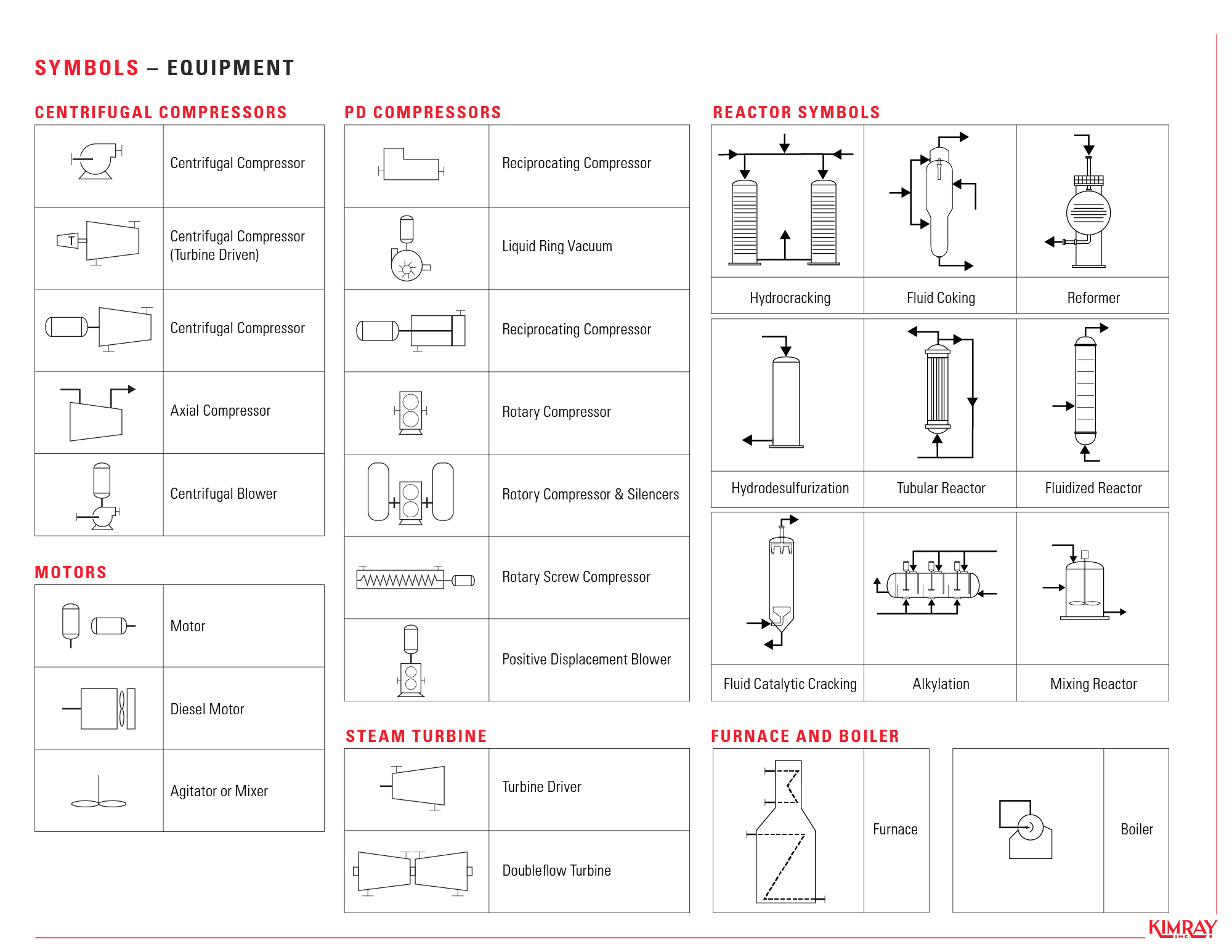
How To Read Oil And Gas P Id Symbols Kimray
The PID is the primary schematic drawing used for laying out a process control systems installation.

Isa p&id symbols. How it is done. Standard PID Symbols Legend Industry Standardized PID Symbols Piping and Instrument Diagram Standard Symbols Detailed Documentation provides a standard set of shapes symbols for documenting PID and PFD including standard shapes of instrument valves pump heating exchanges mixers crushers vessels compressors filters motors and. The symbols are organized in sections including equipment fire and safety flow elements instrumentation piping valves and more.
Works with metric and imperial drawing units. Further while process flow diagrams PFDs are well understood by that name piping and instrument diagrams PIDs may exist under various. Symbols conform to ISA Standard 51-2009.
To indicate the control system architecture associated with the process. The measuring instrument and control device function codes and symbols indicate which process parameter is being measured the. ANSI A - F and ISO.
Exchangers like the one featured on the PID and in the picture are temperature-changing. A PID piping and instrumentation diagram is a graphic representation of the piping and system components in your process that uses standard symbols and annotations. DCS and PLC symbols became a necessity with the computerization of process automation.
These symbols are assembled on the drawing in a manner that clearly defines the process. Visio PID features Industry Standard PID Symbols Libraries. A piping and instrumentation diagram PID is a graphic representation of a process system that includes the piping vessels control valves instrumentation and other process components and equipment in the system.
Requests in PI diagrams and data exchange between PID tools for PCE-CAE tools 14 ISA 51 Instrumentation Symbols and Identification. Symbol legend sheets are included. PID symbols are a graphical representation of physical equipment that installed on the field.
- 3 - ANSIISA-51-2009 Preface informative This preface is included for information purposes and is not part of ANSIISA-51-2009. Copy projSymbolStyledwg from project 1. PID Equipment Symbols The common PID equipment symbols are organized into ten categories.
PID Symbols for Valves. P. The primary purpose of using codes and symbols is to enable the various instrument functions required in a process to be clearly and concisely represented on Process Flow Diagrams PFD and on Pipeline and Instrumentation Drawings PID.
C - Users choice. Pumps and Turbine PID Symbols. Process PID 1.
PIC001 -DB 001 Appendix DB 1 Hygienic Process Piping Legend Sheet PIC001 -DB 002 Appendix DB 3 Hygienic Process Equipment Legend Sheet. Media piping class material pressure temperature. It plays a big role in the management of a physical process.
ISA PID symbols will inform the Process Operator and Control Room Operator where the control components are located. Replace the projSymbolStyledwg in project 2 with file from project 1. Many types of valves are required in a process plant for flow regulation or onoff purpose.
This subcommittee will utilize symbols and identification per ANSIISA-51-2009 Instrumentation Symbols and Identification in combination with other ISA standards commonly used equipment symbols and practitioner experience. If you see a square with a diamond in it on a PID that means a PLC is part of the control process. PIC001-C-002 Appendix C-2 Example Process PID 2-C-003 Appendix C-3 Example Utility PID.
The SP53 committee in developing ISA-53 Graphic Symbols for Distributed ControlShared Display Instrumentation Logic and Computer S ystems The key elements of ISA-53 have been incorporated into ISA-51 and it is the Societys in tent to withdraw ISA-53 after publication of this revision of ISA-51. Loop numbers for tags are taken from the valve tag as shown on each pid that references this detail. Atmospheric tanks Compressors Blowers Drivers Filters Heat exchangers Heaters HVAC Pumps Stacks Vessels Atmospheric Tanks.
Type of valve employed depends on nature of fluid flow control required operating pressure and temperatures as well as surround atmosphere. DCS control components that are viewable andor accessible on DCS screens will have ISA symbols with square boxes drawn around them. NOTE It is the overall ISOTC10SC10 plan to withdraw ISO 3511 all parts.
To be of continuing value this standard. ANSIISA-61804 and the batch standards ANSIISA-88 Parts 1-3 have been adopted by many designers of modern control systems for graphics design and documentation of the control system. There are few ISO and British standards available that provide symbols and best practices to draw PFD and PID such as ISA S51 BS 5070 and ISO 10628.
71 Plot Plan It is often helpful to look at the plot plan to get an overview of how a plant is physically organized. PID SYMBOLS ISA Symbols and Loop Diagrams f PIDs Piping and Instrumentation Diagrams or simply PIDs are the schematics used in the field of instrumentation and control Automation The PID is used to by field techs engineers and operators to better understand the process and how the instrumentation is inter connected. D - Users choice.
This standard has been prepared as part of the service of ISA The International Society of Automation toward the goal of uniformity in the field of industrial automation. The PID standard issued by PIP is enclosed in PIP PIC001 Piping and Instrumentation Diagram Documentation Criteria which defines the PID format drawing size item layout tag format text arrangement etc symbols drafting rules and tagging and numbering scheme for the equipment tanks exchangers pumps reactors etc piping piping lines valves and fittings and. This approach will work for few cases where the internal class name defined for each asset is identical in both standards.
To indicate the instruments or control devices attached to the process. Here is a list of symbols for various types of valves used in process industry. If you see a square box drawn around the circle on a PID that means a DCS is part of the control process.
Appendix D PIDs for the Hygienic Processing Industries. 5Now try to place symbols from ISA palette to the drawing in PIP Metric project. Intelligent standard libraries ANSI ISO 10628 IEC 62424 ISA-51 and dynamic symbols with associated attributes and relationships.
The instrumentation and control IC symbols used in PIDs are generally based on ISA-51-1984-R1992 Instrumentation Sym-bols and Identification2. Contains 335 PID symbols in dwg format and 78 custom line types. - an aecom company 1.
Equipment drivers and instrumentation and controls. PID SYMBOLS ISA Symbols and Loop Diagrams Process Instrumentation Diagram PID Purpose 1. Measured or Initiating Variable.
I - Current electrical J - Power. First letter indicates a measured or initiating variable or a modifier such as Current I Speed S or Flow F. F - Flow rate.
All symbols and drawing elements have associated data properties eg. The graphical symbols have already been transferred to. B - Burner combustion.
2


No comments