Social Items

PID symbols exist for all major components and lines such as valves vessels instruments pumps compressors and towers. Further while process flow diagrams PFDs are well understood by that name piping and instrument diagrams PIDs may exist under various.

P Id And Pfd Drawing Symbols And Legend List Pfs Pefs

It plays a big role in the management of a physical process.
Isa p&id symbols legend. The ANSIISAs S51 standards are what this guide will be using to communicate consistently. Symbols conform to ISA Standard 51-2009. B - Burner combustion.

These two-dimensional diagrams function as a blueprint for the engineering systems design. PID symbols are a graphical representation of physical equipment that installed on the field. These symbols main function is to illustrate the systems process rather than serve as a map.

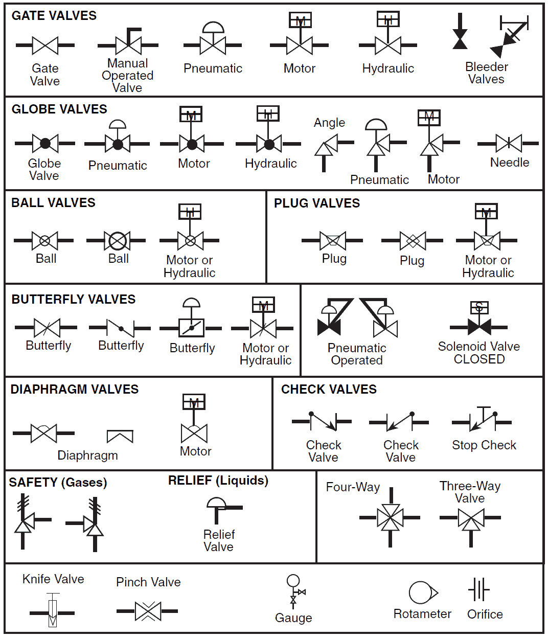
Creating a Symbol PID Legend prior to the design stage help project engineers organize and keep track of the systems process flow efficiently. For Multi-port valves such as 3-way and 4-way the structure of the symbol is similar having a triangle to represent each port or way. Whats a piping and instrumentation diagram PID.

This standard has been prepared as part of the service of ISA The International Society of Automation toward the goal of uniformity in the field of industrial automation. To be of continuing value this standard. Most PIDs will show these as heavy lines with arrows on the lines.

Pumps and Turbine PID Symbols. Legend Symbol. SYMBOLS AND ABBREVIATIONS USED IN PID legends.

Free Download PID Symbol Legend PDF File. These are fundamental to every standardized engineering project. Many ISA standards were developed through collaboration with.

About PID symbols Piping and instrumentation diagrams or PIDs are used to create important documentation for process industry facilities. The SP53 committee in developing ISA-53 Graphic Symbols for Distributed ControlShared Display Instrumentation Logic and Computer S ystems The key elements of ISA-53 have been incorporated into ISA-51 and it is the Societys in tent to withdraw ISA-53 after publication of this revision of ISA-51. Orifice Plate Turbine Primary Element Positive Dispalcement Type with Flow Totalizing Indicator Flow Switch Non Intrusive Element Restricted Orifice Orifice Plate with Quick Change Fitting Annubar Element VenturyType Flow Element Nozzle Type Flow Element.

Contains 335 PID symbols in dwg format and 78 custom line types. These ISA instrumentation symbols provide the user with graphic symbols to be used during the engineering design and layout for various instrumentation-related activities including. Standard PID Symbols Legend Industry Standardized PID Symbols Piping and Instrument Diagram Standard Symbols Detailed Documentation provides a standard set of shapes symbols for documenting PID and PFD including standard shapes of instrument valves pump heating exchanges mixers crushers vessels compressors filters motors and.

Ie shown in fig below. AutoCAD PID symbols standards. I - Current electrical J - Power.

PIC001-B-002 Appendix B-2 Typical Instrumentation Legend Sheet. AutoCAD PID has four different symbol standards templates JIS ISA PIP ISODIN. The shapes in this legend are representative of the functional relationship between piping instrumentation and system equipment units.

Piping and instrument diagrams PID Symbols Process Flow Diagrams PFD Logic diagram development. Measured or Initiating Variable. PID is an abbreviation meaning Piping and Instrumentation Diagram.

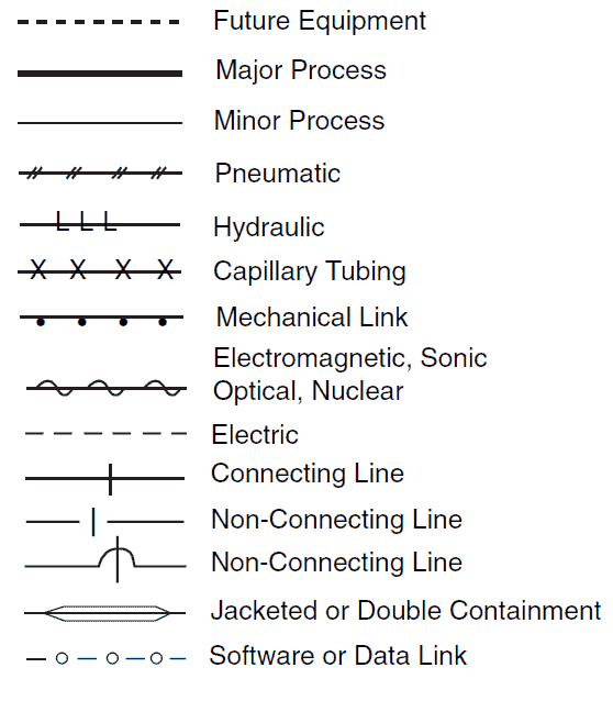
The arrows show the direction of flow. Symbol legend sheets are included. As a general rule the standards mentioned in this article are used as reference.

All of the valves represented above are 2-way inline valves that are used for flow control either onoff or throttling. The ISA51 is a standard for PID symbols. The ISA S51 ISO 10628 and BS 5070 cover the standardization of PID symbols and guide process engineers in their plant design activities.

This article is a summary of the different existing standards on the symbology and methodology to create a PIDSome of these standards such as the ISA are more than 20 years old and have been considered in the absence of other documents as de facto standards in the international industry. The most common PID symbols are listed below. Where to find all PID symbols.

Piping Instrumentation Diagrams PIDs - Punchlist Zero. PIC001-B-001 Appendix B-1 Typical Piping Legend Sheet. F - Flow rate.

PFD PLANT225220 DA6502 DRAWING CONTROL DA6500 SYMBOLS LEGEND DA6501 FEED FROM 220-E-350 AS BUILT. Free Download PID Software and Get Editable Symbols. A Symbol PID Legend Reading instructions shown below is a document that depicts all the symbols and labels used in the main PID.

Main Process Lines are the major pipelines in a process system. Piping and Instrumentation Diagrams are graphical representations of a process system. Works with metric and imperial drawing units.

Auxiliary secondary Process Lines are pipes that feed into the main process line or draw from the main process line. A PID piping and instrumentation diagram is a graphic representation of the piping and system components in your process that uses standard symbols and annotations. Depending on your companys standards guidelines templates and region the one you use will vary.

PFD symbols May change from company to company BS 5070 ISO 10628 and ISA S51 12. The instrumentation and control IC symbols used in PIDs are generally based on ISA-51-1984-R1992 Instrumentation Sym- bols and Identification2 This book will aid in solving the long existing and continuing problem of confusing information on PIDs. With EdrawMax you would be exposed to a broad range of different PID symbols as well as a variety of their templates.

Piping components pipes flanges and. PIC001-B-003-1 Appendix B-3 Driven Equipment Legend Sheet PIC001-B-003-2 Appendix B-3 Heat Transfer Equipment Legend Sheet. This subcommittee will utilize symbols and identification per ANSIISA-51-2009 Instrumentation Symbols and Identification in combination with other ISA standards commonly used equipment symbols and practitioner experience.

C - Users choice. Shown here are PID symbols for the most common valve types. D - Users choice.

P. Appendix B Legend Sheets. The engineering company that is creating the PID normally has standards that they follow in the creation of this document.

Its important to start with the correct standard as changing later will require remapping of your entire diagram. ANSI A - F and ISO. - 3 - ANSIISA-51-2009 Preface informative This preface is included for information purposes and is not part of ANSIISA-51-2009.

First letter indicates a measured or initiating variable or a modifier such as Current I Speed S or Flow F. Process Example Process PID 1. Not all PID elements are standardized but the instrumentation symbols follow a standard set by the International Society of Automation ISA.

There are few ISO and British standards available that provide symbols and best practices to draw PFD and PID such as ISA S51 BS 5070 and ISO 10628.


How To Read An Oil Gas P Id With Control Valve Symbols Explained Ansi Isa 5 1 Youtube


Isa P&id Symbols Legend

PID symbols exist for all major components and lines such as valves vessels instruments pumps compressors and towers. Further while process flow diagrams PFDs are well understood by that name piping and instrument diagrams PIDs may exist under various.


P Id And Pfd Drawing Symbols And Legend List Pfs Pefs

It plays a big role in the management of a physical process.

Isa p&id symbols legend. The ANSIISAs S51 standards are what this guide will be using to communicate consistently. Symbols conform to ISA Standard 51-2009. B - Burner combustion.

These two-dimensional diagrams function as a blueprint for the engineering systems design. PID symbols are a graphical representation of physical equipment that installed on the field. These symbols main function is to illustrate the systems process rather than serve as a map.

Creating a Symbol PID Legend prior to the design stage help project engineers organize and keep track of the systems process flow efficiently. For Multi-port valves such as 3-way and 4-way the structure of the symbol is similar having a triangle to represent each port or way. Whats a piping and instrumentation diagram PID.

This standard has been prepared as part of the service of ISA The International Society of Automation toward the goal of uniformity in the field of industrial automation. To be of continuing value this standard. Most PIDs will show these as heavy lines with arrows on the lines.

Pumps and Turbine PID Symbols. Legend Symbol. SYMBOLS AND ABBREVIATIONS USED IN PID legends.

Free Download PID Symbol Legend PDF File. These are fundamental to every standardized engineering project. Many ISA standards were developed through collaboration with.

About PID symbols Piping and instrumentation diagrams or PIDs are used to create important documentation for process industry facilities. The SP53 committee in developing ISA-53 Graphic Symbols for Distributed ControlShared Display Instrumentation Logic and Computer S ystems The key elements of ISA-53 have been incorporated into ISA-51 and it is the Societys in tent to withdraw ISA-53 after publication of this revision of ISA-51. Orifice Plate Turbine Primary Element Positive Dispalcement Type with Flow Totalizing Indicator Flow Switch Non Intrusive Element Restricted Orifice Orifice Plate with Quick Change Fitting Annubar Element VenturyType Flow Element Nozzle Type Flow Element.

Contains 335 PID symbols in dwg format and 78 custom line types. These ISA instrumentation symbols provide the user with graphic symbols to be used during the engineering design and layout for various instrumentation-related activities including. Standard PID Symbols Legend Industry Standardized PID Symbols Piping and Instrument Diagram Standard Symbols Detailed Documentation provides a standard set of shapes symbols for documenting PID and PFD including standard shapes of instrument valves pump heating exchanges mixers crushers vessels compressors filters motors and.

Ie shown in fig below. AutoCAD PID symbols standards. I - Current electrical J - Power.

PIC001-B-002 Appendix B-2 Typical Instrumentation Legend Sheet. AutoCAD PID has four different symbol standards templates JIS ISA PIP ISODIN. The shapes in this legend are representative of the functional relationship between piping instrumentation and system equipment units.

Piping and instrument diagrams PID Symbols Process Flow Diagrams PFD Logic diagram development. Measured or Initiating Variable. PID is an abbreviation meaning Piping and Instrumentation Diagram.

The arrows show the direction of flow. Symbol legend sheets are included. As a general rule the standards mentioned in this article are used as reference.

All of the valves represented above are 2-way inline valves that are used for flow control either onoff or throttling. The ISA51 is a standard for PID symbols. The ISA S51 ISO 10628 and BS 5070 cover the standardization of PID symbols and guide process engineers in their plant design activities.

This article is a summary of the different existing standards on the symbology and methodology to create a PIDSome of these standards such as the ISA are more than 20 years old and have been considered in the absence of other documents as de facto standards in the international industry. The most common PID symbols are listed below. Where to find all PID symbols.

Piping Instrumentation Diagrams PIDs - Punchlist Zero. PIC001-B-001 Appendix B-1 Typical Piping Legend Sheet. F - Flow rate.

PFD PLANT225220 DA6502 DRAWING CONTROL DA6500 SYMBOLS LEGEND DA6501 FEED FROM 220-E-350 AS BUILT. Free Download PID Software and Get Editable Symbols. A Symbol PID Legend Reading instructions shown below is a document that depicts all the symbols and labels used in the main PID.

Main Process Lines are the major pipelines in a process system. Piping and Instrumentation Diagrams are graphical representations of a process system. Works with metric and imperial drawing units.

Auxiliary secondary Process Lines are pipes that feed into the main process line or draw from the main process line. A PID piping and instrumentation diagram is a graphic representation of the piping and system components in your process that uses standard symbols and annotations. Depending on your companys standards guidelines templates and region the one you use will vary.

PFD symbols May change from company to company BS 5070 ISO 10628 and ISA S51 12. The instrumentation and control IC symbols used in PIDs are generally based on ISA-51-1984-R1992 Instrumentation Sym- bols and Identification2 This book will aid in solving the long existing and continuing problem of confusing information on PIDs. With EdrawMax you would be exposed to a broad range of different PID symbols as well as a variety of their templates.

Piping components pipes flanges and. PIC001-B-003-1 Appendix B-3 Driven Equipment Legend Sheet PIC001-B-003-2 Appendix B-3 Heat Transfer Equipment Legend Sheet. This subcommittee will utilize symbols and identification per ANSIISA-51-2009 Instrumentation Symbols and Identification in combination with other ISA standards commonly used equipment symbols and practitioner experience.

C - Users choice. Shown here are PID symbols for the most common valve types. D - Users choice.

P. Appendix B Legend Sheets. The engineering company that is creating the PID normally has standards that they follow in the creation of this document.

Its important to start with the correct standard as changing later will require remapping of your entire diagram. ANSI A - F and ISO. - 3 - ANSIISA-51-2009 Preface informative This preface is included for information purposes and is not part of ANSIISA-51-2009.

First letter indicates a measured or initiating variable or a modifier such as Current I Speed S or Flow F. Process Example Process PID 1. Not all PID elements are standardized but the instrumentation symbols follow a standard set by the International Society of Automation ISA.

There are few ISO and British standards available that provide symbols and best practices to draw PFD and PID such as ISA S51 BS 5070 and ISO 10628.


How To Read An Oil Gas P Id With Control Valve Symbols Explained Ansi Isa 5 1 Youtube


Show comments
Hide comments

No comments